Led Circuit Diagram And Working Principle Learn the basics of LED circuit diagrams and how to create a basic LED circuit with a few components. Follow the step-by-step guide and experiment with different resistor values to adjust the brightness of the LED.

Learn how to connect LEDs with different power sources and what type of current limiting resistor to use. See diagrams and details for 3V, 6V, 9V and 12V LED circuits.

Simple LED Circuit Diagram
I = LED current (we had been using 20 mA in our other calculations but since wiring LEDs in parallel draws more current I had to multiply the current that one LED draws by the total number of LEDs I was using. 20 mA x 2 = 40 mA, or .04A. And my values for the formula this time were: R = (9V - 1.7V) / .04A

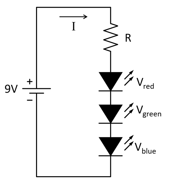
Here is a diagram of the basic circuit. Just as before, the LED positive side is connected to the battery's positive side, and likewise negative to negative. The current will flow from the battery through the resistor and LED and then back to the battery. The resistor and LED are connected in series, which means one after the other.

Step Guide: How to Make a Simple LED Circuit Diagram
Learn how to build a simple LED circuit using a resistor and a battery on a breadboard. Find out the polarity of LED, the resistor value calculation and the basic LED circuits. Learn how to wire LEDs in series and parallel circuits with diagrams and examples. Find out the advantages and disadvantages of each circuit type and how to power them with constant current LED drivers. Learn how to build simple LED circuits using single, series and parallel LEDs with 12V supply. See the circuit diagrams, components required, principle of operation and resistor calculations for each circuit.